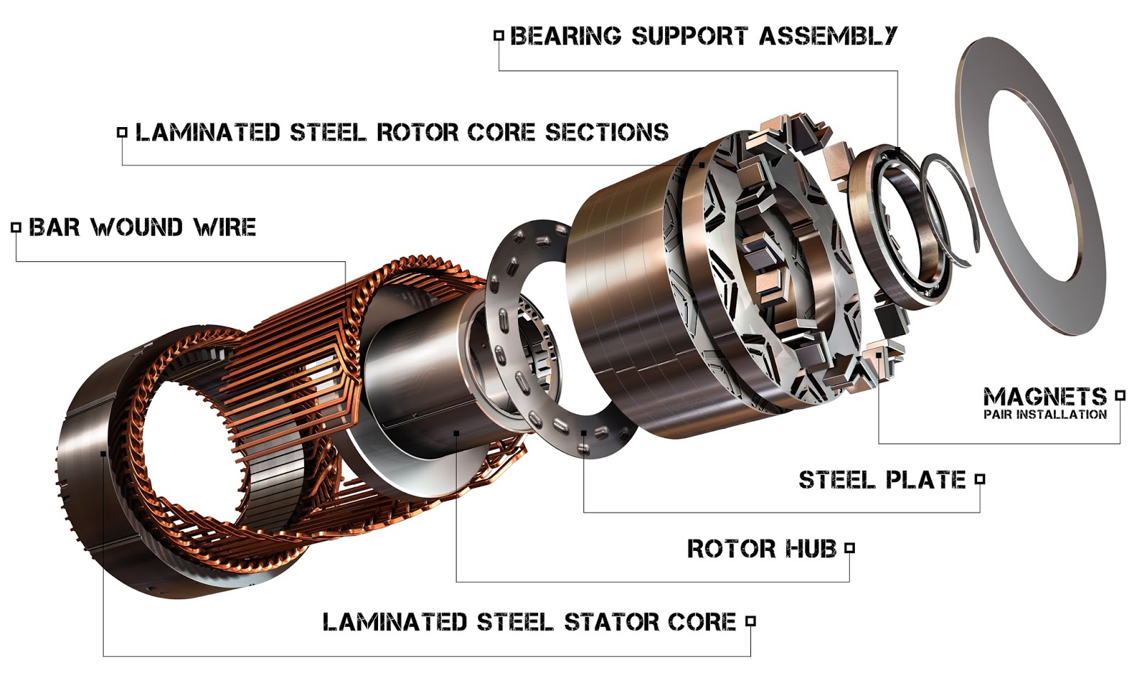
Car Parts Rotor Diagram
Rotor parts made motor wire plastic tb training coil magnet which gif electromagnet consists form illustration salvo Rotor stator between difference cage squirrel core cylindrical made What is step motor stack length?
Repair Guides
Rotor motor length stack stator step bearings single diagram next Repair guides Construction disc brakes rotor working types braking principle materials
Stator rotor alternator difference between construction definition electrical circuitglobe
Wheel bearings bearing rotor hub replace change diagram assembly outer diagrams remove brake labels part do nut useStator rotor lamination fig2 Motor induction cage slip squirrel ring motors wound components basic different starting rotor phase stator rings electric alternator between typeHow to replace wheel bearings.
Figure 2-22.rotor assemblyMagnet electric permanent motors construction motor parts vehicles synchronous exploded pm hybrid earth Alternator componentsBrake disc parts diagram brakes system rotor caliper drum rotors single automotive job wheel braking replaced pakwheels vs piston simple.

Alternator howstuffworks alternators mechanic wires electricity rotating engine plow shaft
Difference between stator & rotor (with comparison chart)Brake rotor diagram disc rotors hub repair front assembly guide shield blown cherokee fig | repair guidesDifference between stator & rotor (with comparison chart).
Rotor parts plastic motor which made exchange stackOuter rotor motor (left), inner rotor motor (right) [6] Disc brakes: construction, working principle, types, and rotorThe basic elements of slip ring induction motors.
![Outer Rotor Motor (Left), Inner Rotor Motor (Right) [6] | Download](https://i2.wp.com/www.researchgate.net/profile/Prathamesh_Dusane/publication/303895443/figure/download/fig23/AS:668587186462738@1536415015839/Outer-Rotor-Motor-Left-Inner-Rotor-Motor-Right-6.png)
Rotor diagram
Stator and rotor laminationDistributor engine wiring 1967 exploded cylinder v8 type gm conventional repair coil point guide electrical 1963 transistorized installation fig corvette What parts are replaced during a disc brake job?- pawlik automotive.
.


